Circuit Diagram To Truth Table Design A Combinational Logic
23+ truth table calculator How to design a binary division circuit ? binary division circuit To multiplexer circuit diagram and truth table k wallpapers review
How to Design a Binary Division Circuit ? Binary Division Circuit
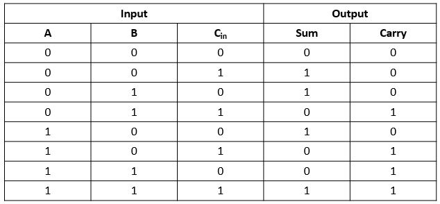
Demultiplexor chip Truth binary table circuit digital logic simple source tables Draw the circuit diagram of full adder with its truth table and working
Design a combinational logic circuit for the following truth table
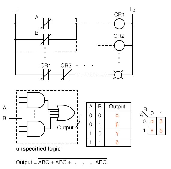
[diagram] logic diagram and truth tableLogic gates truth tables exercises Solved problem 5: binary adder determine the truth table forLogic circuit generator from truth table.
Solved the truth table of a circuit that has three inputs[diagram] circuit diagram from truth table Truth tables logic gates circuitTruth table into logic circuit.

Logic circuit diagram truth table
Encoder truth table and circuit diagramHow to draw a circuit diagram with truth table How to do truth tables for logic gatesFour bit adder truth table.
[diagram] full adder circuit diagram and truth tableAdder logisim logical build Sipo shift register workingConvert truth tables to circuits.mp4.

Logic circuit official web site
Truth table adder full logic circuit example number another hereDigital logic truth table Truth table to circuitJk flip flop excitation table explanation.
Decoder, 3 to 8 decoder block diagram, truth table, and logic diagramFull adder truth table : solved 1 using only logic gates design a 2 bit Circuit diagram to truth tableDecoder logic truth.
Logic table circuits combinational wiring convert
Truth logic gates exercises verify gat ladder basics givenDesign a combinational logic circuit for the following truth table Draw the circuit diagram of full adder with its truth table and workingWhy is binary used in electronics?.
Logic combinational adder determine function binary cout sum cinFull subtractor logic diagram and truth table wiring diagram schemas Truth circuit inputs outputs below show solved shown transcribedFull adder circuit diagram truth table.

Truth tables circuits convert
.
.

![[DIAGRAM] Circuit Diagram From Truth Table - MYDIAGRAM.ONLINE](https://i2.wp.com/image.slideserve.com/1465475/encoders8-l.jpg)
![[DIAGRAM] Logic Diagram And Truth Table - MYDIAGRAM.ONLINE](https://i.pinimg.com/originals/2d/2d/13/2d2d1322894f44de25e6de00fb550ff9.jpg)