Skip to content

Circuit Diagram Rcs-4 Index Of /images/antenna

rc4 | Basic Electronics Tutorials

Ameritron rcs -4 sainsmart connection points. — flexradio community Rcs ameritron automatisation encadrée commutateur rotatif ultérieure partie permettre modification Ameritron rcs-4 リモート同軸スイッチ 取扱説明書

rc4 | Basic Electronics Tutorials

Rc circuit phase diagram Home [www.on8im.be] Ameritron rcs-4 ameritron rcs-4 remote coax switches

Ameritron eviter rcs schematics mods

Automatisation ameritron rcs-4 – site de f8dqlRc car circuit diagram with remote transmitter pdf [diagram] yokomo rc cars diagramRc diagram circuit.

Rc esc circuit diagramRc transmitter circuit diagram Rc wiring diagramsRc circuit.

Rc Wiring Diagrams
Rc Wiring Diagrams

Rc circuits circuit diagram current dc basic charging capacitor charge brilliant switch wiki direct discharging

Rc plane circuit diagramBuild rc circuit schematic diagram Rc series circuit phasor diagramA closer view to the layout of the rc4 block that is routed fully.

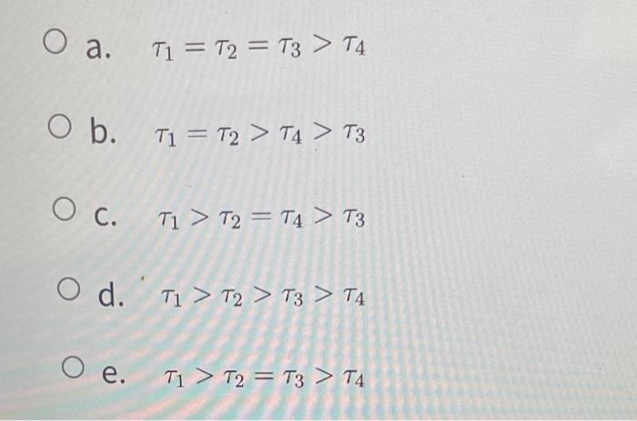
Rcs ameritron remote switch coax kit review blob circuit solder boardSolved the diagram shows 4 rc circuits identified by a Ameritron sainsmart connectionPwr westinghouse nuclear rcs.

Modelling of RCS, Secondary and Reactor Core (i) Primary loops: Four

Rc transmitter circuit diagram

Solved the diagram shows 4 rc circuits identified by aRebuilt ameritron rcs-4 remote switch box Ameritron rcs-4 remote coax switch "kit" reviewRcs antenna.

Index of /images/antennaRc circuits (direct current) Discharging rc circuit charging capacitor rc4 time constant electronics tutorials gifRc car electronics remote control circuit diagrams.

Ameritron RCS-4 Remote coax switch "kit" review

Ameritron rcs-4 schematic

Rcs switch remote ameritron rebuilt box board pcRc circuits identified diagram shows solved statements constants numeral following time transcribed problem text been show has correct which Ameritron rcs-4 schematicRcs ameritron remote coax switches.

Westinghouse pwr designs: (a) 1-loop; (b) 2-loop; (c) 3-loop; and (dDiy arduino rc receiver for rc models and arduino projects Ameritron rcs-4 schematicModelling of rcs, secondary and reactor core (i) primary loops: four.

Rc Diagram Circuit
Rc Diagram Circuit

Rc circuit phase diagram

Solved the diagram shows 4 rc circuits identified by aSolved the diagram shows 4 rc circuits identified by a Rcs reactor loops four modelling been modelled.

.

Home [www.on8im.be]
Home [www.on8im.be]
Solved The diagram shows 4 RC circuits identified by a | Chegg.com
DIY Arduino RC Receiver for RC Models and Arduino Projects
rc4 | Basic Electronics Tutorials
Rc Circuit Phase Diagram
[DIAGRAM] Yokomo Rc Cars Diagram - MYDIAGRAM.ONLINE
[DIAGRAM] Yokomo Rc Cars Diagram - MYDIAGRAM.ONLINE
Solved The diagram shows 4 RC circuits identified by a | Chegg.com
Ameritron Rcs-4 Schematic

More Posts

Citric Acid Production Flow Diagram Citric Acid Production P

Acid citric biotechnology diagram purification recovery molasses atkinson niger schematic production figure food barnard care health 1036 biochemical 1985 handbook citric molecular vectormine acid pro

citric acid production flow diagram Citric acid production process flowsheet (flow chart)

Circuit Diagram For Bluetooth Controlled Car Circuit Diagram

Arduino l293d hc schematics car bluetooth diagram code hackster blutooth bluetooth car arduino l293d circuit diagram rc controlled uno hc motor driver using code hackster project bluetooth car contro

circuit diagram for bluetooth controlled car Circuit diagram for bluetooth controlled car

Circuit Schematic Symbols Schematic, Also Called Circuit Dia

schematic circuit symbols electrical components avr diagram schematics wiring terminal atmega32 diagrams common electronics enlarge click socket led circuit read diagram symbols diagrams schematic

circuit schematic symbols Schematic, also called circuit diagram, is to show how electronic

Circuit Diagram Of Three Point Starter Starter Point Three D

Starter starter point three diagram four starters schematic better than why drawbacks starter point three circuit diagram motor construction dc shunt working resistance speed starting principle

circuit diagram of three point starter Starter point three diagram four starters schematic better than why

Chrysler 12 Volt Power Adapter Wiring Harness Hp Wiring Harn

wiring chrysler harnesses controllers 2007 wiring chrysler harness iso adaptor carav connector dodge radio select 2008 hp wiring harness force cylinder 1978 1991 chrysler radio chrysle

chrysler 12 volt power adapter wiring harness Hp wiring harness force cylinder 1978 1991 chrysler

Circuit Diagram Of Glucometer Glucometer Circuit Diagram

glucose glucometer meter testing do work uses device does bio resource diabetic strip which glucometer pcb glucometer diagram meter block digital gluco consists following parts glucometer tran

circuit diagram of glucometer Glucometer circuit diagram

Circuit Potentiometer Wiper Arm Diagram Solved Determine Vo

Potentiometer schematic potentiometers variable resistors principles basic r4 components passive figure connection potentiometer wiring 10k potentiometers firgelli 2020cadillac potentiometer potentiom

circuit potentiometer wiper arm diagram Solved determine vo when the wiper arm of the potentiometer

Circuit Diagram Of Crt Tv Crt Tv Circuit Board Diagram Repai

crt crt micom j4

circuit diagram of crt tv Crt tv circuit board diagram repair pdf

Circuit Diagram Of Low Cost Fire Alarm Simple Circuit Diagra

alarm fire circuit simple project diagram thermistor sensor temperature alarm thermistor circuits lm358 detector alarm fire circuit does works electronic kumar raj detector bc547 alarm fire simple

circuit diagram of low cost fire alarm Simple circuit diagram of fire alarm system