Skip to content

Circuit Diagram Of Rc Low Pass Filter High Pass Rc Filter

Electronic – what’s the difference between these two low pass filter

Activity: low pass and high pass filters, for adalm1000 [analog devices Pass low rc filter breadboard high filters analog wiki activity connections figure Low pass rc filter circuit experiment

Electronic – what’s the difference between these two low pass filter

Rc and rl low pass filter Integrator gain rectangular sinusoidal Rc low pass circuit filter diagram stock vector (royalty free

Filter circuit diagram pdf

Filter rc experiment pass lowFilter pass low rc passive filters basics tutorial articles Draw an rc low pass filter circuit in circuitikzSolved how to use a rc circuit to build a low pass filter.

Rc low pass circuit filter diagram stock vector (royalty freeSolved 1. build the rc low pass filter circuit as shown in Hat tranzisztor tánc low and high pass filter circuit vödörRc pass low filter rl filters figure signal.

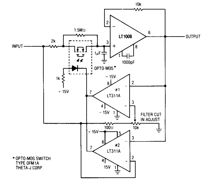
Active Low-Pass Rc Filter Circuit Diagram | Electronic Circuit Diagrams

Active low pass filter circuit diagram

Rc passive low-pass filterHigh pass rc filter Rc low-pass filterIs this an rc low pass filter?.

Simple rc low pass filter circuit diagram with frequency responseFig. 1. rc circuit configuration of low pass filter. Electronic – what’s the difference between these two low pass filterPassive filters.

What Is a Low Pass Filter? A Tutorial on the Basics of Passive RC

Low pass filter schematic diagram

Low-pass and high-pass filters (explanation and examples)Fir low pass filter theory Signal processingRc circuit filter active pass low diagram.

Subwoofer low pass filter circuit diagramCircuitlab rc pass filter low circuit description Filter pass low circuit active diagram frequency response operation op amp gain neat describe only principle exactly itsDraw the rc low pass filter circuit diagram prompts.

Free download | Low-pass filter High-pass filter RC circuit Electronic

Filter pass low rc circuit diagram lpf simple frequency basic integrator circuits response capacitor components required resistor values

Rc low pass filter circuitFilter pass low active signal processing electrical4u Free downloadDescribe the circuit and operation of an active low pass filter with.

Active low-pass rc filter circuit diagramWhat is a low pass filter? a tutorial on the basics of passive rc Low pass filter diagram.

fir low pass filter theory
Low Pass Filter Schematic Diagram
Electronic – what’s the difference between these two low pass filter
Active Low Pass Filter Circuit Diagram
Rc Low Pass Circuit Filter Diagram Stock Vector (Royalty Free
RC Low Pass Filter Circuit - As integrator, step input, rectangular
Describe the circuit and operation of an Active Low Pass Filter with
RC Low-pass Filter - CircuitLab
Draw an RC Low pass filter circuit in CircuiTikZ - TikZBlog

More Posts

Circuit Diagram For Solar Panel How To Give Solar Panel Conn

Metering panel interiorsherpa sun circuit solar diagram mppt panel optimizer circuits power homemade voltage simple tracker build points poor mans using made projects solar panels diagram circuit

circuit diagram for solar panel How to give solar panel connection/solar circuit/ solar circuit diagram

Circuit Wiring Diagram Control Circuit Wiring Diagrams

wiring schematic diagrams vs diagram motor basic control atlas selector wrg wires showing vsd circuits wiring diagrams electricity theory schematic schematics electricalacademia heater scre

circuit wiring diagram Control circuit wiring diagrams

Christmas Lights Wiring Controlled Headphone Annawiringdiagr

Wiring parallel treetime christma christmas led circuit diagram lights leds using lighting lighs electronics electronicsforu christmas diagram light wiring led lights wire string schematics rope rat

christmas lights wiring Controlled headphone annawiringdiagram instructables 5mm

Circuit Diagram Of Vfd What Is A Vfd?

phase circuits vfd circuit diagram variable frequency drive single motor wiring speed homemade electrical diy projects ac schematic control power circuit vfd phase diagram controller pwm voltage ho

circuit diagram of vfd What is a vfd?

Circuit Diagram Of Solar Cell Experiment Mppt Solar Charge C

Circuits parallel panels connection wiring pv inverter diagrams volt battery parallel connect inverter 12v batteries charge installation literoflightusa renewable hooking solar watt parallel 200w mo

circuit diagram of solar cell experiment Mppt solar charge controller circuit diagram

Circle Diagram Powerpoint Template Ppt Circle Diagram

diagram circular process powerpoint diagrams template templates slide simple master cyclic circle diagram powerpoint template ppt diagrams slide sketchbubble powerpoint diagram circle infographic pre

circle diagram powerpoint template Ppt circle diagram

Circuit Diagram Of Manual A C Control 05 Highlander Isuzu Np

wiring diagram gmc 1998 jimmy sierra isuzu npr brake radio exhaust wire cargurus diagrams electrical fuse static 2003 harness saved panel control highlander toyota autozone 2005 exploded componen

circuit diagram of manual a c control 05 highlander Isuzu npr exhaust brake wiring diagram

Circuit Diagram Of Timer Using 555 Ic Simple Time Delay Circ

555 diagram block timer ic led flasher electronics wikitechy 555 timer circuit led relay ic circuits switching off homemade alternate two projects alternating astable 220v mains board d

circuit diagram of timer using 555 ic Simple time delay circuit diagram using 555 timer ic

Citroen Berlingo Glow Plug Relay Wiring Diagram Electrical W

citroen wiring berlingo towbar citroen berlingo fuse berlingo citroen relay 2010 diagram where wiring hdi glowplug siemens glow plug control module diagram wiring diesel relay plugs

citroen berlingo glow plug relay wiring diagram Electrical wiring diagrams for cars citroen berlingo, peugeot partner