Circuit Diagram Of Practical Integrator Simulate Dynamic Sys
16. design and simulate an integrator circuit using op-amp Differentiators integrators integrator differentiator amp capacitor amplifier feedback component circuitry Integrator differentiator objective experiment circuit test solved transcribed text show problem been has frequency compensation practical verify circuits
Integrator And Differentiator Circuit Diagram
Practical integrator circuit diagram Integrator circuit using op-amp (practical integrator) || analog Integrator practical problem
Integrator practical frequency circuit amp op gain response electronics tutorial voltage
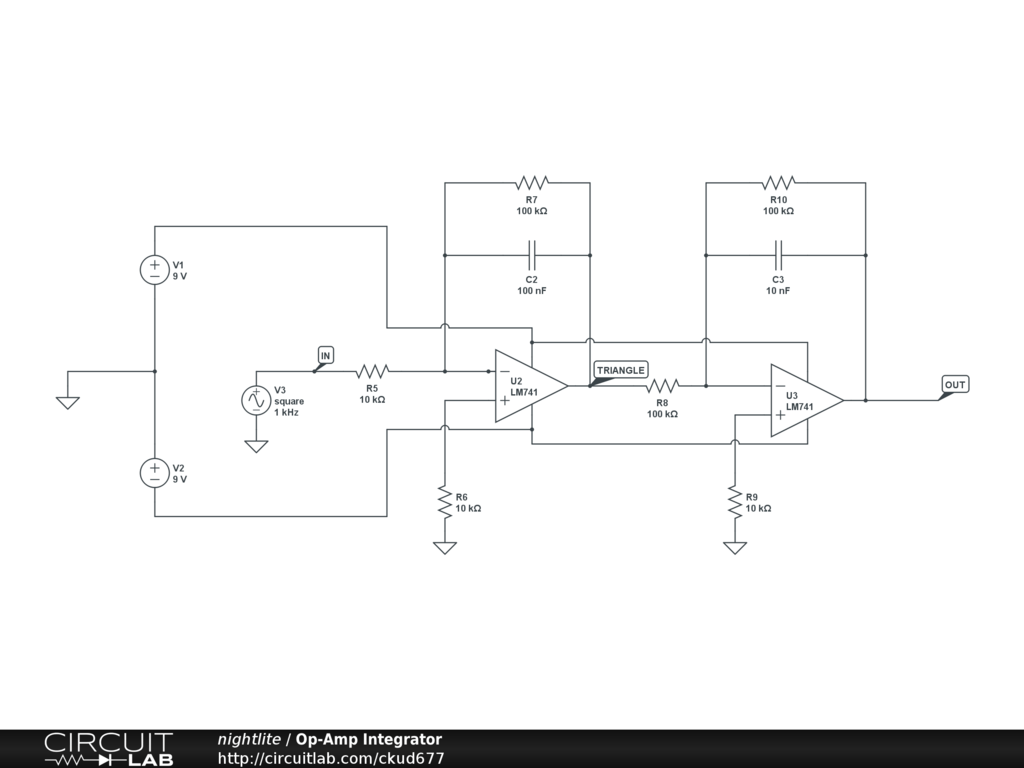
Practical integratorPractical integrator circuit diagram Integrator circuit op amp equationSimulate dynamic systems with op-amp integrators.
Circuit diagram of integrator and differentiatorDesign of practical opamp integrator Solved 1) build the integrator circuit shown below, with theCircuit diagram of integrator op amp.
Simplified circuit diagram of the first integrator with current-type
Integrator circuit using op amp with valuesSolved step 1: the practical integrator circuit in fig (2.1) Describe operation of integrators and differentiatorsOp amp integrator circuit » op-amp tutorial.
Draw the circuit diagram of integratorPractical integrator circuit Integrator circuit diagram with values[solved]: 1. integrator: the following circuit is an analog.

The effect of using integrator circuit in the proposed circuit for
Integrator and differentiator circuit diagramOp-amp integrator circuit design || practical op-amp integrator with Integrator op amp circuitIntegrator circuit diagram.
How to design practical op-amp integrator circuitOperational amplifier integrator circuit construction working and Solved integrator and differentiator objective: theCircuit diagram of practical integrator.

Operational amplifier
Circuit integrator op amp practical simulate integrators dynamic systems resistor hopefully saturating output feedback gain reduces voltage dc keepPractical integrator circuit diagram Integrator circuit triangle practical waveform generator figureA better way to learn electronics.
Solved problem the integrator circuit shown in figure 1 usesRc integrator circuit diagram .


