Circuit Diagram Of Decimal Adder Bcd Adder Em Digital Logic
Full adder : circuit diagram, truth table, equations & verilog code 2 bit adder circuit diagram Verilog subtractor
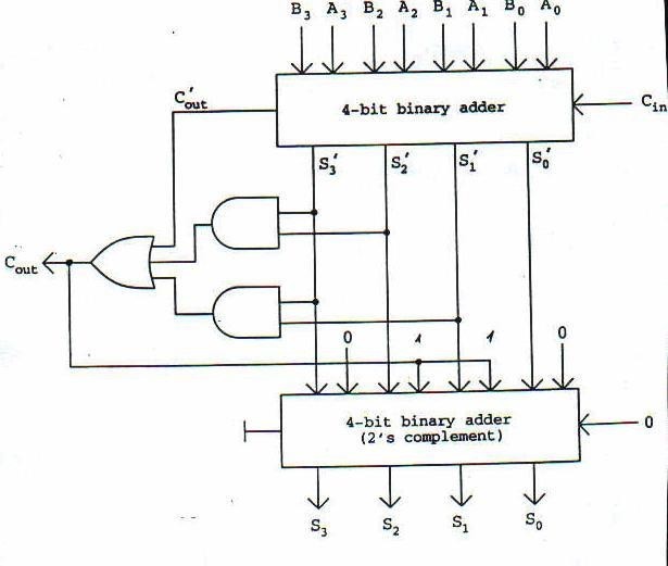
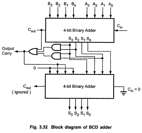
BCD Adder in Digital Logic - GeeksforGeeks
4 bit binary adder subtractor vhdl code 83+ pages summary [3.4mb Bcd adder in digital logic Download 4 bit adder circuit stick and logic diagram
4 bit binary subtractor circuit diagram
Circuit diagram of decimal adderAdder bcd Bcd binary adder logic digital decimal geeksforgeeks implement electronics sum codedCircuit adder full truth table its logic theory gates gate xor diagram circuits construction construct tables elcho seat visit.
Adder xor carry rangkaian ripple adders sum theorycircuit schematic transistor kombinasi10+ half adder diagram [diagram] 4 bit adder circuit diagram waveformFull adder circuit diagram.

Decimal adder
Digital logic design: bcd adderFull adder circuit – how it works Bcd adder circuit4 bit adder circuit diagram.
Bcd adder em digital logic – acervo lima🎉 4 bit parallel adder theory. 5.9: four. 2022-10-30 Circuit design decimal adderConstruct a circuit for bcd adder.
![[DIAGRAM] Block Diagram Bcd Adder - MYDIAGRAM.ONLINE](https://i2.wp.com/static.javatpoint.com/tutorial/digital-electronics/images/decimal-or-bcd-adder2.png)
Jelaskan perbedaan half adder full adder dan paralel adder pada
4 bit bcd adder circuit diagramFull adder circuit – how it works [diagram] block diagram bcd adderBlock diagram of basic full adder circuit.
Adder logicBcd adder Half adder working principleAdder decimal.
![[DIAGRAM] 4 Bit Adder Circuit Diagram Waveform - MYDIAGRAM.ONLINE](https://i2.wp.com/www.researchgate.net/profile/Saman_Amarasinghe/publication/37595015/figure/download/fig7/AS:309873876193289@1450891097709/Full-Adder-Circuit-Diagram.png)
3 bit adder schematic
Adder circuit full diagram basic gates using truth tableFull adder circuit diagram 4 bit adder circuitAdder theorycircuit.
Adder bcd logic circuit input digital two shown figure willSolved draw a circuit diagram of the serial adder showing How to construct truth tables logic gatesFull adder circuit diagram using ic.

Circuit diagram for 4 bit binary adder using ic 7483 » wiring core
.
.