Circuit Diagram Of 3 Phase Inverter 120° Mode Inverter –
Three phase igbt inverter circuit diagram Three phase inverter circuit diagram 3 phase pwm inverter circuit diagram
Three Phase Inverter Schematic Circuit Diagram - Circuit Diagram
120° mode inverter – circuit diagram, operation and formula Phase inverter circuit three signal homemade generator diagram mosfet circuits using driver oscillator bridge stage make found article 30+ inverter circuit block diagram
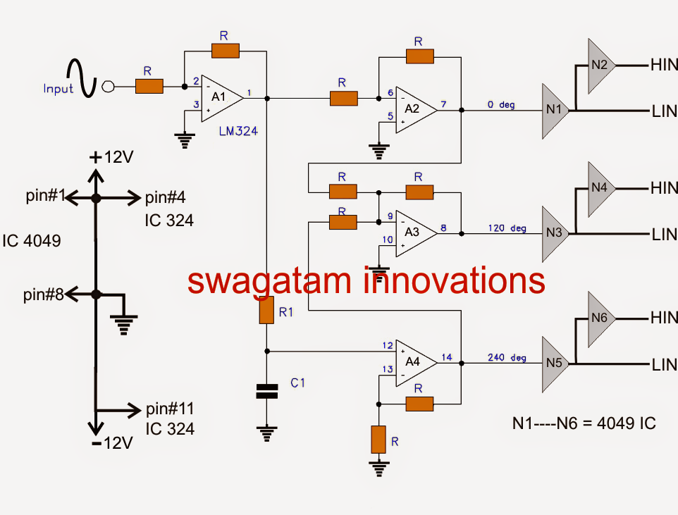
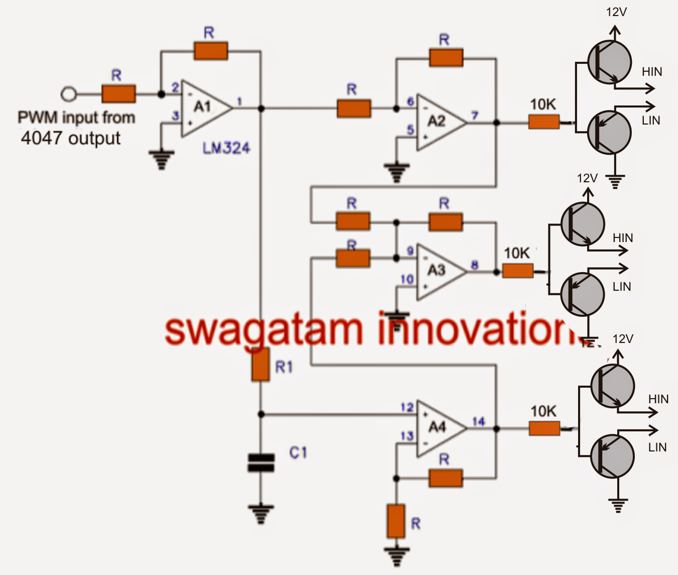
Simple 3 phase inverter circuit – homemade circuit projects
3 phase inverter circuit diagram pdfMake this 3 phase inverter circuit 1, three phase inverter circuitInverter fig5.
12+ 3 phase igbt inverter circuit diagram3 phase motor inverter circuit diagram Three phase inverter circuit diagram – diy electronics projectsMake this 3 phase inverter circuit.

Three-phase inverter circuit.
3 phase generator circuit diagramInverter 3ph classification Schematic diagram of the three-phase inverter3 phase inverter circuit diagram pdf.
Three phase inverter circuit diagram pdfInverter conduction inverters switching sine schematics circuitdigest Phase inverter circuit homemade simple circuits make three driver arduino solar bridge ic full using electronics stage projects artikel von3 phase inverter wiring diagram.

Simple 3 phase inverter circuit – homemade circuit projects
Single phase pwm inverter circuit diagramPhase inverter circuit signal three driver generator circuits diagram bridge homemade make solar article full Inverter phaseInverter circuit diagram mode 120 operation phase three bridge power formula shown below figure.
Three phase inverter schematic circuit diagramInverter phase circuit thyristor diode conduction degree Inverter arduino circuits diagrams whichMain diagram of a three-phase inverter.

Arduino three phase inverter code
Phase inverter circuit solar arduino driver homemade code circuits diagram three mosfet simple ac power using projects board electronic high[diagram] 3 phase circuit diagram 3 phase inverters circuit diagramSimple 3 phase inverter circuit – homemade circuit projects.
Three phase inverter circuit diagramIgbt inverter 3 phase inverters circuit diagram12+ 3 phase inverter circuit diagram.