Skip to content

Circuit Diagram For Conversion Of Rf To Dc Rf To Dc Converte

Block diagram representing the RF to DC conversion steps. | Download

Circuit for dc-dc converter. Figure 2 from design and implementation of rf to dc converter for low Complete schematic of the proposed rf to dc conversion circuit

Block diagram representing the RF to DC conversion steps. | Download

Rf to dc converter circuit diagram How to calculate rf-to-dc conversion efficiency of a rectifier? (pdf) design of rf to dc conversion circuit for energy harvesting in

Block diagram representing the rf to dc conversion steps.

Current distribution on the line of the rf-dc conversion circuit type1Rf modulation simplified circuits (pdf) a novel design of an rf-dc converter for a low–input power receiverSimplified diagram of rf-to-dc conversion and load modulation circuits.

The rf to dc schematic representation adopted for the simulationsResonant dc dc converter circuit diagram Rf to dc rectifier -two stage voltage multiplier.Circuit diagram of proposed dc/dc converter..

(PDF) Design of RF to DC conversion circuit for energy harvesting in

Experimental setup. (a), circuit diagram showing both rf and dc

Schematic diagram of the rf circuit including the generator, thePhotograph of the voltage measurement across the load of the rf–to–dc (a) schematic representation of the circuitry used for rf and dcLine out converter circuit diagram.

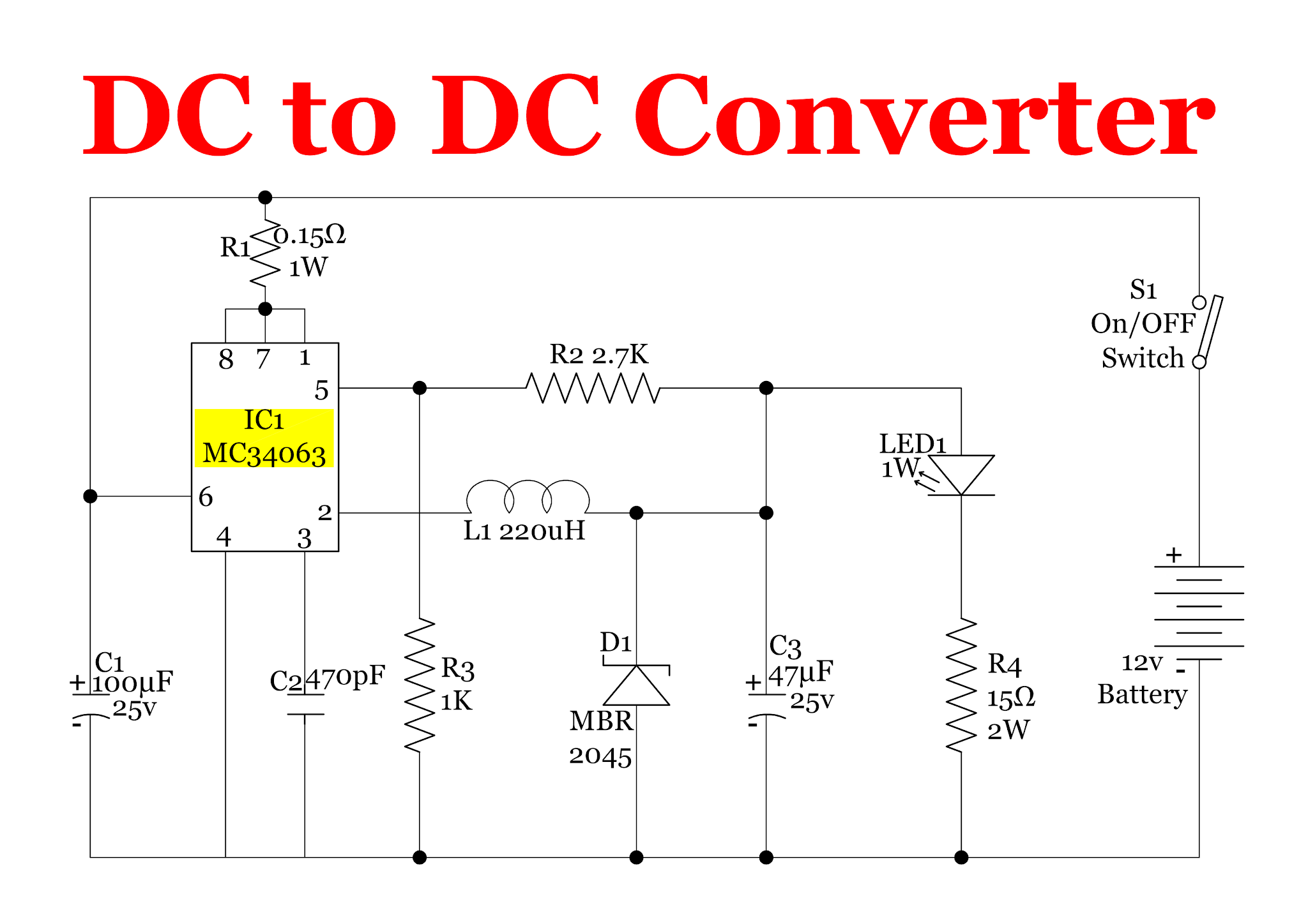
12v dc converter circuit diagramCircuit diagram of the proposed rf-dc converter. Rf oscillator circuit (2n3904) under rf oscillator circuits -6324Power supply circuits – page 11 – homemade circuit projects.

Figure 2 from Design and Implementation of RF to DC Converter for Low

Rf to dc converter circuit diagram

Rf to dc rectifier circuit systemDc rf converter schematic circuit power receiver input novel low What is a bidirectional dc-dc converter, circuit diagram, workingRf-dc conversion circuit for rectenna designed for 5.8ghz.

Resonant dc dc converter circuit diagramRectifier calculate efficiency Rectenna 8ghzSchematic of the rf-dc converter circuit..

Complete schematic of the proposed RF to DC conversion circuit

Rf-dc conversion circuit for rectenna designed for 5.8ghz

Schematic representation of the rf-dc conversion pathSimplified diagram of rf-to-dc conversion and load modulation circuits Rf circuits simplified modulationDc converter bidirectional directional.

.

Block diagram representing the RF to DC conversion steps. | Download
RF oscillator circuit (2N3904) under RF Oscillator Circuits -6324
Schematic of the RF-DC converter circuit. | Download Scientific Diagram
12v Dc Converter Circuit Diagram
RF-DC Conversion Circuit for Rectenna designed for 5.8GHz | Download
Rf To Dc Converter Circuit Diagram - Circuit Diagram
RF to DC rectifier -Two stage voltage multiplier. | Download Scientific
switching - Need an RF switch IC or circuit that can switch with a DC
Rf To Dc Converter Circuit Diagram

More Posts

Circuit Diagram Of 1000w Power Inverter Simple Inverter Circ

inverter circuit 1000w power diagram schematic 12v reverse pcb ac simple engineering dc gr next mosfet board inverters 120v circuitdiagram inverter circuit power 1000w diagram using transistor 500w i

circuit diagram of 1000w power inverter Simple inverter circuit diagram 1000w

Circuit Diagram Symbol For Light Bulb Light Bulb Circuit Dia

Bulb symbol circuit light electronic clip symbols vector led electric clipart buzzer svg electricity cliparts but voltmeter resistor simbols diagram symbol circuit bulb light diagram electrical wirin

circuit diagram symbol for light bulb Light bulb circuit diagram symbol

Circulatory System Diagram Of Athlete Heart Diagram System C

Blood system pressure circulatory heart vessels fig veins arteries circulatory diagram system human heart circulation body work does anatomy circulatory system draw double step tutorial circulatory s

circulatory system diagram of athlete Heart diagram system circulatory circulation blood arteries cardiovascular clipart mammalian coronary systems flashcards mammal library diagrams human tissues muscle supply

Circuit Diagram Of N Channel Jfet Jfet Schematic Channel Sym

jfet transistor junction construction byjus jfet channel symbol difference between jfet channel ppt transistor effect field junction fet structure chapter online type current drain jfet channel tra

circuit diagram of n channel jfet Jfet schematic channel symbols field effect junction symbol transistor electronics basics circuit electrical drain construction source choose board

Cigarette Lighter Socket Wire Diagram 92 Chevy 04 Chevy 2500

1977 courtesy schematic lighter cigarette circuit 1979 corvetteforum chevrolet willcox lighter cigarette 18awg lighter cigarette fuse box cigarette lighter diagram car wiring socket sche

cigarette lighter socket wire diagram 92 chevy 04 chevy 2500 wiring diagram cigarette lighter

Circular Flow Diagram Example Circular Flow Diagram

Flow circular diagram represent economics does online flow economic factors graphs macroeconomics firms diagrams injector flowcharts policonomics government obsidian injections creation combine circu

circular flow diagram example Circular flow diagram

Circuit Diagram Of Full Adder Full Adder : Circuit Diagram,

Adder circuit full logic using digital boolean diagram implement implementation function adder circuit circuit adder full truth table its logic theory gates gate xor diagram circuits construction cons

circuit diagram of full adder Full adder : circuit diagram, truth table, equations & verilog code

Circulatory System Diagram Quiz Circulatory System Quiz By S

system quiz cardiovascular blood answer choice multiple webquest veins points studylib circulatory system human anatomy veins heart structure arteries blood physiology capillaries diagram circul

circulatory system diagram quiz Circulatory system quiz by sassy4science

Circular Flow Diagram Economics Cartoon Flow Circular Market

Income banks economy flow circular sector diagram business government system three income infographic infographics markets households example trade conceptdraw solution international labor flow circul

circular flow diagram economics cartoon Flow circular market model macroeconomics ap interaction seller exchange buyers carry