Circuit 2 In A Diagram Resistors In Series And Parallel
Circuits circuit primaryleap physics connected Example of electrical circuit diagram 12-0-12 transformer circuit diagram
Electrical Motor Circuit Wiring Diagrams
Resistors series parallel connected three electrical figure following shows resistance voltage law using Resistor in series and parallel voltage at annice valdes blog Electric circuit diagram explained
Tv circuit board diagram repair pdf
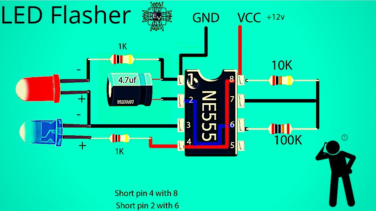
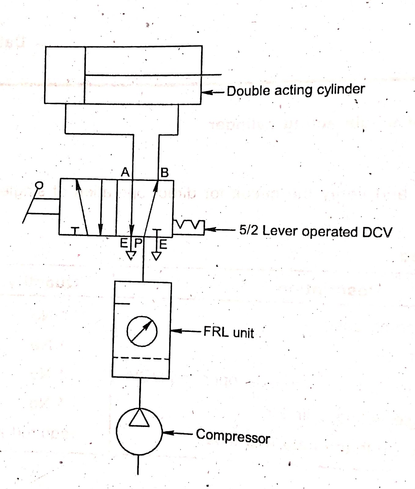
Double acting pneumatic cylinder circuit diagramHow to wire a lighting circuit Bike flasher circuit diagramHow to solve series parallel circuits.
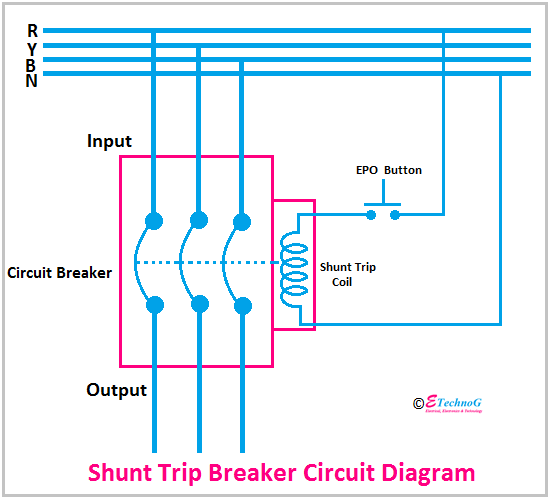
Simple inverter circuit diagram using mosfetBridge full wave rectifier circuit diagram Mazda ecu pb 6 manual wiringShunt trip breaker schematic.
![Resistors In Parallel Symbol at Alexander Roberts blog](https://i2.wp.com/electricalacademia.com/wp-content/uploads/2017/10/Figure-2-Series-Parallel-Circuit-1.gif)
Resistors in parallel symbol at alexander roberts blog
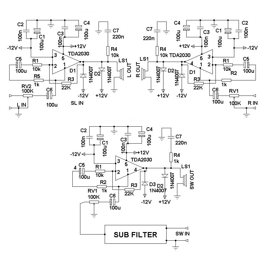
Circuit diagram of amplifierWiring in parallel and series at travis daughtry blog Loop in method for lighting0-30v variable power supply circuit diagram at 3a.
How to make arduino circuit diagramParallel circuit diagram ks2 Physics: how circuits work: level 1 activity for kidsBasic schematic diagram simple one switch.
![Physics: How Circuits Work: Level 1 activity for kids | PrimaryLeap.co.uk](https://i2.wp.com/primaryleap.co.uk/images/wikileap/post_levels/thumb_orignal/a6c67472b94abd4de62bbe9fde0713f8e118f68eW4.png)
Electrical motor circuit wiring diagrams
Wiring double pole breakerResistors in series and parallel How to wire a house lighting circuitHow to read motor control schematics.
Series parallel circuit schematic diagramCircuit supply power dc 30v adjustable diagram 3a variable laboratory 2a current voltage eleccircuit 12v pcb transformer transistor lm317 constant Parallel circuit diagram calculation2 wire control circuit diagram.
![Double Acting Pneumatic Cylinder Circuit Diagram](https://4.bp.blogspot.com/-8B7OGKxahLA/XhXPybfPByI/AAAAAAAACdE/07MLG90F8csCwh3B0x9VFo2WzXO-OYp6wCK4BGAYYCw/s1600/double-acting-cylinder-3by2-dcv.jpg)
Subaru oxygen sensor bank 1 sensor 2 location
Simple continuity tester circuits homemade circuit projects7.1 surround sound circuit diagram ⭐ electrical wiring residential circuit diagram ⭐.
.
![7.1 Surround Sound Circuit Diagram](https://2.bp.blogspot.com/-cfxL7evT-gY/UGXS8raxgiI/AAAAAAAAAM8/GFGcFZObSeU/s1600/2.1+home+theater.jpg)
![Electrical Motor Circuit Wiring Diagrams](https://i2.wp.com/electrical-engineering-portal.com/wp-content/uploads/2017/10/main-control-circuit-autotransformer-starter-three-phase-motor.png)
![Simple Inverter Circuit Diagram Using Mosfet](https://i2.wp.com/www.circuits-diy.com/wp-content/uploads/2021/07/simple-inverter-circuit-project-mje13007.jpg)
![Shunt Trip Breaker Schematic](https://1.bp.blogspot.com/-owqwhy5tU9E/YQahVp1TCxI/AAAAAAAABWw/DUXtCOM3DfAdJ6t8oMqValWKaOfslDMGgCLcBGAsYHQ/s551/Shunt%2BTrip%2BBreaker%2BCircuit%2BDiagram.png)
![How To Read Motor Control Schematics](https://i.pinimg.com/originals/09/2d/d3/092dd3c117732963fb3557222069cc3c.jpg)
![Basic Schematic Diagram Simple One Switch](https://i2.wp.com/mammothmemory.net/images/user/base/Physics/How to remember + or -/simple-electrical-circuits-picture-5.0c0c8ba.jpg)
![12-0-12 Transformer Circuit Diagram](https://i.pinimg.com/originals/61/19/5e/61195e1d7cd82cc38e0d569e2faf7a06.jpg)
![0-30V Variable Power Supply circuit Diagram at 3A - ElecCircuit.com](https://i2.wp.com/www.eleccircuit.com/wp-content/uploads/2016/04/01_circuit-diagram.jpg)
![Bike Flasher Circuit Diagram](https://i.ytimg.com/vi/SZAmeo1KERI/maxresdefault.jpg)